Isolation Table
Home
Dynamic
Magnet
The
isolation table was designed to hold various equipment including a
microscope above the magnet. When the pole cylinder is being
turned, there are huge tangential forces exerted on the dynamic magnet
base. Although this base is constructed of steel and
probably weighs a ton, these forces are sufficiently large to shake the
table! To overcome the effect of these vibrations on a
microscope, an isolation table was designed to float above the dynamic
magnet.
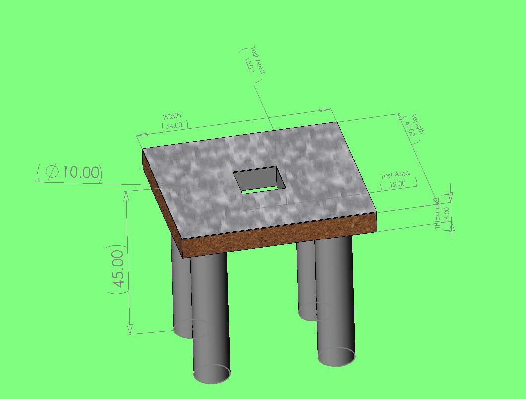
The table is an MDF frame with a construction foam interior for
strength. On the top is a 1/4" Al plate with 1"x1" 1/4-20 square
hole pattern for mounting hardware. The amount of metal used in
the table construction was limited to reduce stray magnetic fields and
eddy currents during dynamic operation. The screws used were
stainless steel for their nonmagnetic/nonconducting properties.
The table sits on four air isolation chambers which in turn sit on four
concrete columns. The isolation chambers provide an automatically
leveled surface with variable height. They don not, however, have
any other motion controls. This presented a problem as the travel
of the table exceeded the dimensions of the sample area and endangered
sensitive sample and probe equipment. To overcome this dilemma
four steel brackets were attached to the dynamic magnet base
table. A limit stop (long screw) was then added to the brackets
to control the motion of the floating table.


Overall image of the rotating magnet and isolation
table. In this picture you can see the cement bases on which the
isolation columns sit; the motion limiting stops on the front and right
sides; various instruments. Click Here for the SOLIDWORKS
ASSEMBLY file for the floating table.

Front-side image of isolation table.
The probe and microscope motion controls are
visible.


Triple-axis motion control and the transverse Hall
probe are used to characterize the static and dynamic fields.

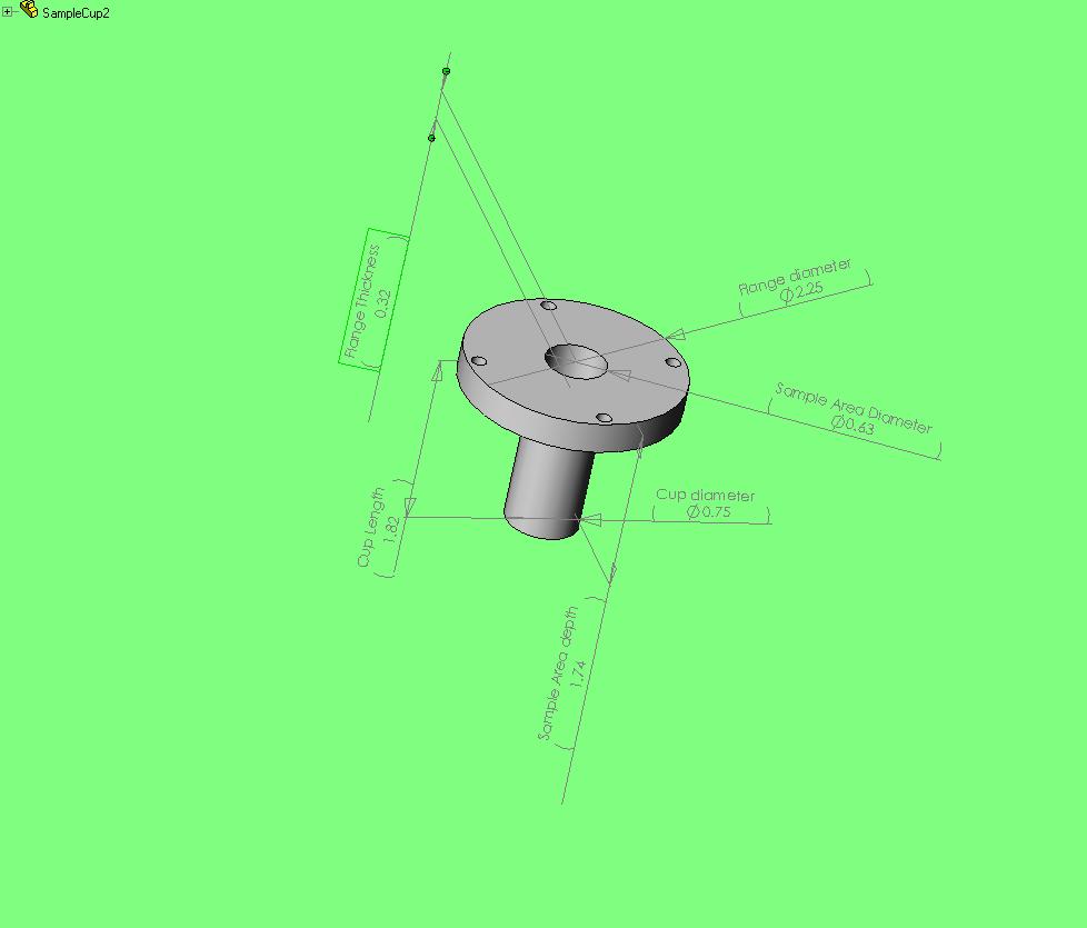
A plexiglass plate is held ~2mm above the rotating
cylinder. Its purpose is to keep stray
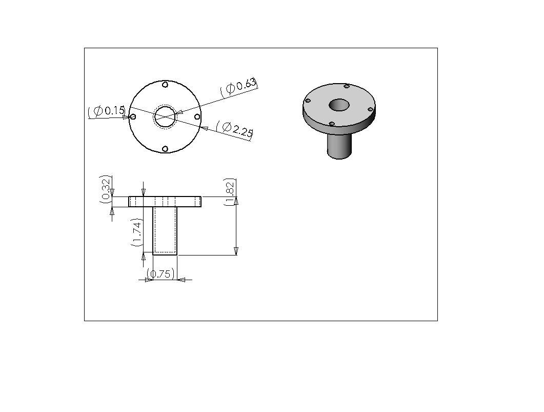
objects from getting stuck between the cylinder and the box. Centered in this plate is a circular cup
designed to keep probes and specimens away from the walls of the
rotating
cylinder. Click Here for the cup as a
SOLIDWORKS PART, and Here for
the SOLIDWORKS DRAWING.
Limit stops (seen above) were
added to keep the probe/sample from hitting the walls of this
protective cup.


Microscope mounted above sample cup. We also have the capabilites
for video capture via our 7X zoom lens. Currently trying to
upgrade the lens for greater zoom, but as you can see from the picture
the working distance has to be significantly large (~50mm).