 Movie of the fracture process (AVI format
750kB)
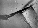
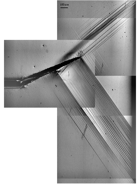
This image shows the fully developed microstructure caused by the high stresses at the crack tip.
This work was done by Galyna Loughan (Vasko) as part of her Ph. D. Thesis.
This research been published:
This specimen provided the most interesting images of the specimens reported in the paper, so it will be discussed here.
If you can't wait the neatest things here they are:
 Movie of the fracture process (AVI format
750kB) Movie of the fracture process (AVI format
750kB) |
This movie shows the fracture process that occurred during the second loading. First the crack grows slowly in a stable manner, then the crack runs quickly during a burst of unstable crack growth. The image below shows the crack after the growth burst in this movie and another smaller burst have occured. See below for still pictures of this process. |
 |
Click for a larger image. This image shows the fully developed microstructure caused by the high stresses at the crack tip. |
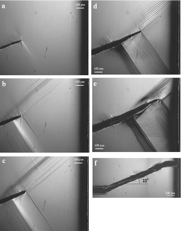
First loading: Microstructure grow off the notch tip and then a crack starts to grow:
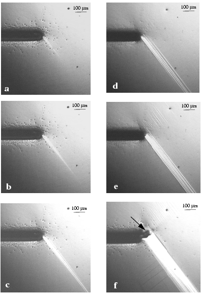
The letters on the pictures above correnspond to the letters on the load-displacement curve below.

After the first loading was completed, the specimen was heated to 80C to remove the microstructure and cooled back to 40C. Then a second loading cycle was performed. Note that the crack runs in an unstable manner between images e and f below.
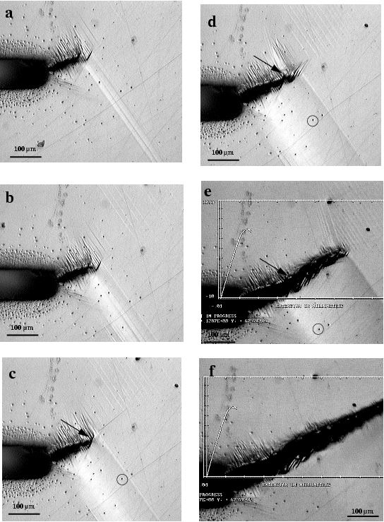
The letters on the images above correspond to the letters on the load displacement curve below.
 The fracture
process in the images above is also in this movie (AVI format 750 kB).
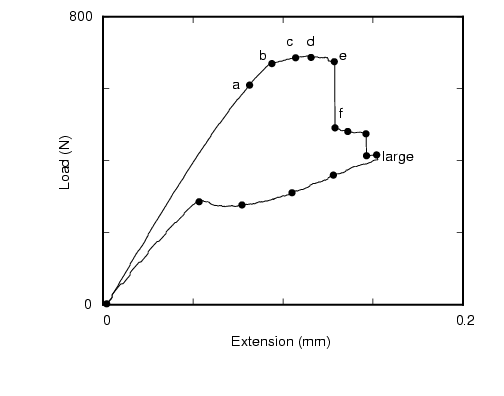
The large coverage image below was taken at the load and displacement marked with the word "large" on the load-displacement curve above. After this image was taken the specimen was unloaded. This image shows the fully developed microstructure caused by the high stresses at the crack tip. It extends all the way to the specimen edge, which is just visible at the right of the image.
The following images show the microstructures disappearing during unloading. These images correnspond to the unmarked symbols on the load-displacement curve above from the one marked large down to zero load.

Note that the crack has closed all the way and that the load-displacement curve shows that all the displacement has been recovered. The crack has not made the specimen any longer!
These images start after the crack growth above and heating to remove all microstructure.
Now the specimen is in two pieces...