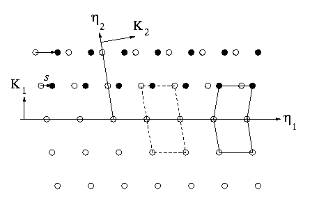
A twin in a crystalline solid occurs between two adjacent regions of the same crystal lattice, where one of the regions is related to the other by a simple shear. At a microscopic level, a twin appears as depicted in Figure 1 below.

Figure 1: Microscopic twin
In Figure 1, the open circles are the lattice points before the
shear; while, the filled circles are the lattice points after the shear.
Further, the dashed line shows two unit cells of the original lattice
before the shear; while, the solid line indicates a unit cell for each
of the lattices after the shear. A twin is also defined by its twinning
elements,  ,
,
 ,
,
 , and
, and
 , some of
which are shown in Figure 1. Specifically, the twin plane normal is parallel
to
  ; the direction
of the twin shear is parallel to
 ; a second
undistorted plane has normal
 ; and an
undistorted vector in this previous plane is parallel to
 . The magnitude
of the twin shear is s .
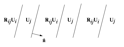
In a martensitic transformation, a twin is formed when two variants of the martensite phase coexist. Macroscopically, they appear is parallel bands alternately containing a different variant. Such a twin can appear as depicted in Figure 2 below.

Figure 2: Macroscopic twins
The twins depicted in Figure 2 can be constructed as follows: two martensite variants Ui and Uj form a variant pair denoted by (i:j), and the compatibility equation for a twinned martensite microstructure with the variant pair (i:j) is written as

The knowns in the equation above are the twin rotation
 , the twin shear
 , and the twin plane
normal
  . Further, this
equation is called the twinning equation.
Solutions exists to the twinning equation if and only if the symmetric matrix Ui-1 Ui2Ui-1 has an eigenvalue equal to one. Moreover, it can be shown that at most two solutions exist to the twinning equation, and for each of these solutions, the twinning elements can be found; from which, the twins are typically either compound (all twinning elements are rational - along crystallographic directions), type I or type II twins.
Symmetry amongst the variants can be used to segregate the variant pairs into sets of symmetry related pairs and into sets of symmetry related twin solutions. This is outlined here.
Various twinned martensite microstructures are possible for different transitions as listed in the table below.
Twinned Martensite Microstructures |
|||
|---|---|---|---|
| Transition | Twin Type | Number | Observed |
| Cubic-to-Trigonal | Compound | 24 | Au-Cd, Terfenol, Ti-Ni, Ti-Ni-Al, Ti-Ni-Fe |
| Cubic-to-Tetragonal | Compound | 12 | Ba-Ti-O3, Fe-Ni-C, Fe-Pd, In-Tl, Ni-Al, Ni-Mn, Ni2-Mn-Ga |
| Cubic-to-Orthorhombic | Compound | 12 | Cu-Al-Ni |
| " | Type I | 24 | Cu-Al-Ni |
| " | Type II | 24 | Cu-Al-Ni |
| Cubic-to-Monoclinic | Compound | 24 | Ti-Ni, Ti-Ni-Cu |
| " | Type I | 72 | Ti-Ni, Ti-Ni-Cu |
| " | Type II | 72 | Ti-Ni, Ti-Ni-Cu |
| " | Not standard twin type | 96 | possible only with special lattice parameters |
In the table above, the first column is the transition; the second lists the type of twin which is possible; the third column lists the number of unique twinned martensite microstructures which can be formed using all of the variants of the martensite phase; and the last column gives some alloys for which some of the twins are observed. This list of materials is by no means exhaustive.
Another microstructure using only the martensite variants is the parallelogram martensite microstructure which is seen in twin crossings.
Top of this page.
Back to the main page.