 (large version, 120k)
To demonstrate and aid in the development of the magnetic field control for the MMTM, a minature compass that uses iron filings was constructed. This compass consists of a 0.062" (1.5 mm) hole milled into plexiglas to a depth of 0.015" (0.4 mm). Into this hole a very small number of iron (mild steel) filings were placed and then a microscope cover slip was glued over the top of the hole. The completed assembly looks like:
 (large version, 120k)
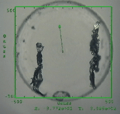
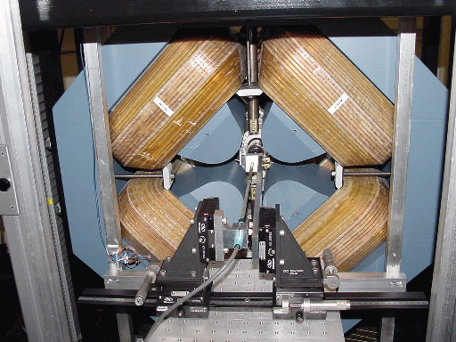
This image was taken thru a color CCD video camera attached to a microscope using dark field illumination. The video signal was digitized by a DV format VCR and recorded on an SGI computer connected to the VCR via an IEEE-1394 (firewire) interface. See the list of MMTM equipment for the details. The image below shows the micro-compass being held between the poles of the magnet (blue) and the gaussmeter probe.

The microscope image shows two sets of filings inside the cavity. The green lines and text in the image are produced by the graphics overlay system of the MMTM instrumentation and the arrow in the middle of the circle shows the magnitude and direction of the applied magnetic field. The scales on the overlay are +/- 500 Gauss.
The movies below show the effect of increasing the magnetic field in the vertical direction and then rotating it 180 degrees clockwise before reducing it back to zero. This causes the iron filings, which are permanently magnetized, to first split into two groups, as shown in the image above, and then rotate, rejoin and complete the 180 degree rotation.
Note that the filings do not levatate in the field, but instead align with the field while one end is touching the edge of the cavity. The magnetic field produced is a minimum at the center of the pole gap and increased toward the poles, thus the center of the field is an unstable equilibrium point and levitation is not possible.