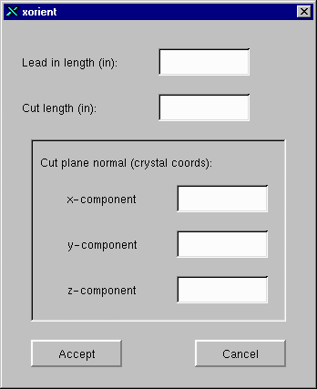
The Xorient program can be used to generate the CNC codes to cut a plane from a specimen with a desired crystallographic normal. Follow the steps below to do this:
First you must enter the correct Holder Notch Angle using the spinbox on the main window. This is the notch on the holder that the boule holder was in when the specimen used for obtaining the x-ray orientations was cut. Typically this is 0.0, but for the example the specimen was cut with the boule holder in the 75 degree notch. The angle for the notch is positive counter-clockwise when looking at the boule holder from the side that the boule extends out of.
Once the correct Holder Notch angle is selected, choose Show... from the EDM menu item. This displays the EDM Sketch Window:
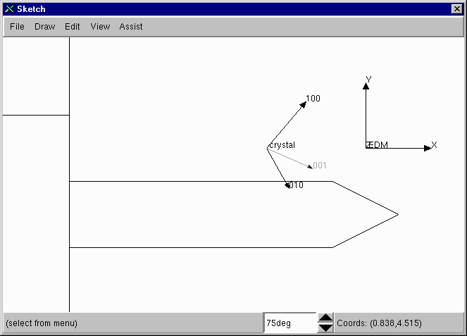
This window shows an outline of the boule mounted on the EDM and the crystal and EDM coordinate systems. The angle at the bottom of the window (75 degrees here) is the notch angle that the boule is mounted in. If you change this setting, the crystal axes rotate to show their orientation for that notch on the holder. The axes are shown as a projection of the 3-D orientation. The axes that have a positive (out of screen) Z component in the EDM coordinates are black and the ones with a negative Z component are shown in gray.
To add an EDM cut, choose Edm Path from the Draw Menu. This brings up the following dialog:

The entries on this dialog are as follows:
Once these values have been entered, click the Accept button. At this point the program will wait for you to click on the main window. This click determines the starting point of the EDM Path. Note that the starting point is only for display purposes, the starting point of the CNC program is always (0,0) and this is set by the location of the EDM wire when the reset button is pressed twice to set the CNC program origin. The window belows shows the EDM Path with values of (0.5, 2.5, 1,0,1) entered into the dialog above:
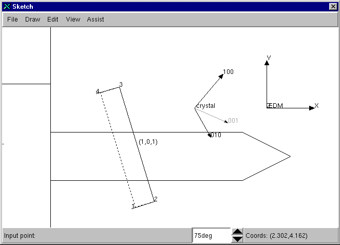
The dashed line on the EDM path is due to the fact that the cut from point 2 to point 3 is a taper cut. The solid line is the top of the wire and the dashed line is the bottom of the wire. The EDM has only a limited range of possible tapers, thus the holder notch must be adjusted to reduce the taper angle to the minimum possible. Click on the spin box at the bottom of the window to change the holder notch being used. In this case the notch at 45 degrees results in the least taper as shown below:
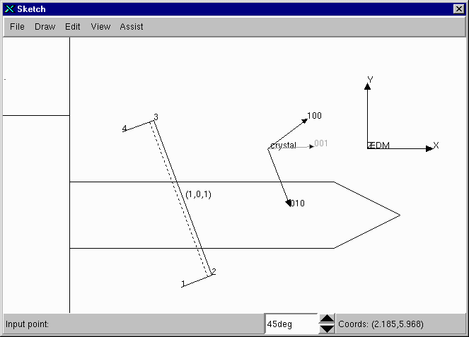
Once the holder notch has been selected, the CNC commands for this path can be saved to a file. Select Save CNC from the file menu. The following notes apply:
The window contents can also be printed with the File/Print item. The CNC output file for the path above contains the following:
Holder notch angle = 45 degrees
Cut normal = (0.707107,0,0.707107)

M80;
M82;
M84;
G90;
G92 X0 Y0;
G01 G41 X0.468307 y0.175182 A2.159733 H01 M90;
G01 G41 X-0.407604 y2.516716 A2.159733 ;
G01 G41 X-0.875911 y2.341534 A0 ;
G40;
M91;
G23;
M02;
This program must be entered into the EDM exactly for the taper cut to work. In addition the Z1, Z2 and Z3 settings on the EDM must be set correctly. The Z settings are defined as follows:
When the machine is cutting on the taper, the U and V values will be non-zero. As a check the angle in the program should equal
atan(sqrt(U*U+V*V)/(Z3+Z4)).
This is because Z3+Z4 is the effective length of the wire between the guides used for taper calculations.
To cut completely oriented slices using the EDM you will want to generate two paths that are perpendicular to each other. One path cuts the face of the plates you wish to cut and the other path is used to put at flat edge on the plate with a known orientation. In this case we also use a 010 plane cut: To get the cut in the orientation below (0,-1,0) was used as the cut normal.
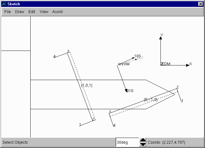
The cuts are then made in the following order:
Note that the best holder notch is the 30 degree notch for this cut, while the 45 is best for the 101 cut, although it appears that both cuts could be done on the 30 degree notch. This is just a coincidence.