
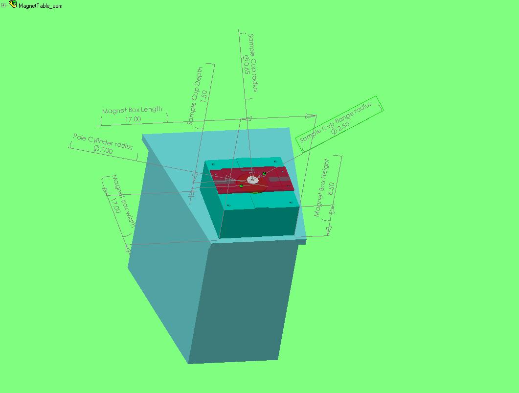
Click Here for the SOLIDWORKS ASSEMBLY file for the magnet setup
Above: Top-side and front-side views of the dynamic magnet setup.
Click Here for the SOLIDWORKS
ASSEMBLY file for the magnet setup
Above: Top-side and front-side views of the dynamic magnet setup.

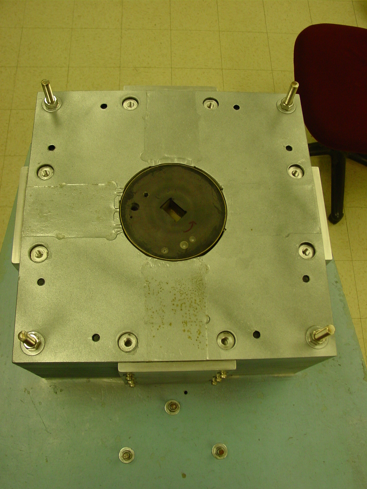
Close-up of the
sample area. The dimensions of the area are
~1in.x.75in.x1.25in. The holes you see in the cylinder are for
balancing.
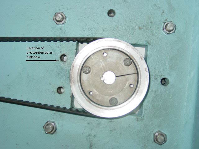


The underside of the
rotating cylinder. A photointerrupter was mounted to a
platform from noted hole.
The photointerrupter will be used to trigger a strobe light so
that we
can precisely time/delay video capture. (NOTE TO SELF include
link to
code for syncing PI and Magnet poles)