![]() Return
to: U of M Home
Return
to: U of M Home
|
|
||

Avionics
|
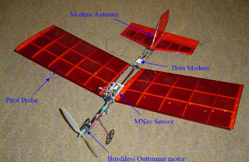
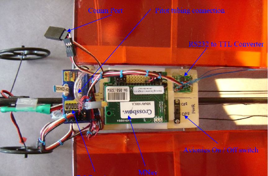
The Avionics hardware: Consists of the following elements, 1. Phytec PhyCore555 based flight control computer (FCC). More 2. Crossbow Micronav Sensor Suite Micronav is a compact and lightweight package well suitable to the weight and volume constraints of miniUAV's but includes of a wide array of integrated sensors like, 3-axis MEMS rate gyros and accelerometers, a 3-axis magnetometer, Air-data system for Ps-Pt measurement and u-blox GPS kernel. The unit also includes an inbuilt 8-channel servo controller board which can be commanded through the bidirectional serial port of the unit. Micronav is a highly configurable system 3. MaxStream Xtend RF data modem and Antenna. More 4. BLDC motor speed controller 5. Futaba RC servos (2 Nos.) 6. RC receiver 7. Accessories- RS232-to-TTL converter, 5V voltage regulator Overview: The figure above shows avionics hardware components integrated onto YardStick R/C airframe . Note that physical separation of the components as been done to minimizde Radio Frequency Interference (RFI) . A pitot probe is placed on the right hand side of the wing with a distance of more than a diameter of propeller length from the centre line of the fuselage so that the air speed measured is not be affect by the propeller wash. Picture below shows the top view of components that are mounted at the CG of the plane. The RC receiver output PWM signal to control the servo actuators and at the same time, a signal line has been hacked into the receiver to provide the PPM control signal that Micronav needs to read the servo command signals. RS232-to-TTL Converter, Pitot proble tubing connection, Avionics On/Off switch, Micoronav serial port and RC Receiver. The power to the avionics system, controlled by the on/off switch, is supplied by a 5 volt regulator which takes in 11.1 volts from the main Lithium-Polymer battery pack (It is rated upto 2.5 amps). The RS232-to-TTL converter is required since Micronav output is in RS232 signals whereas the data modem supports only TTL level serial communication.
However this conversion is required only at the early stages of avionics integration when Micronav is directly communicates with the data modem. In final architecture. the FCC interfaces with data modem and MPC555 core of the FCC supports TTL-UART function, hence the conversion would be unnecessary. A communication port connector access is available onboard so that we can reprogram the data modem for different setup and also we can have a direct access to the MNav without going through the data modem if we need to recalibrate or change setting for the sensor.
Data Modem: The MaxStream data modem is mounted near to the tail of the airplane and its antenna is mounted on the vertical tail so that it will gives the right RF propagation waveform when the modem is communicating with the ground modem. For this data collection task, the modem has been set to 10mW transmission power with a serial data rate of 38.4kbps and an RF throughput of 115Kbps. 4.
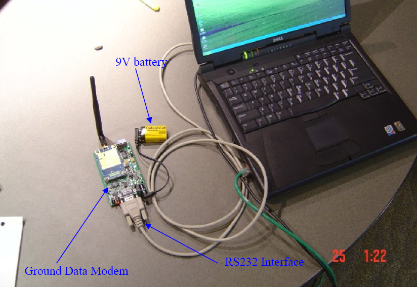
Ground Station:
The ground station has a data modem in the development board and they are powered by a 9v battery. Theinterface of the ground modem and the laptop computer is through a RS232 connection at 38.4Kbps.
|
|