Suman Muppidi
Research Associate
Aerospace Engineering and Mechanics, University of Minnesota
Jets in Crossflow
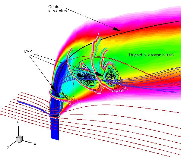
Figure : Isometric view of a jet in crossflow.
Contours of velocity (v) on the symmetry plane indicate the extent of the jet.
Jet cross--section, at various distances along the jet length is shown using contours of us.
Streamlines at these locations indicate the stages of CVP formation.
Streamlines originating in the crossflow fluid show entrainment of the crossflow fluid by the jet.
The term, 'jet in crossflow' refers to a jet of fluid that exits an orifice to interact with the surrounding fluid that is flowing across the orifice. Jets in crossflow are central to a variety of applications such as dilution holes in gas-turbine combustors, fuel injectors, and pollutant dispersion from smoke stacks. In gas-turbine combustors, jets of air issue from the dilution holes, and mix with the crossflow inside the combustor. These dilution jets cool the combustor liners, combustion products, and reduce pollutant formation. Direct numerical simulations (DNS) were used to study the process by which the jet mixes with the crossflow. Deficiencies in presently used scaling laws for jet trajectory were identified, and a new scaling law was proposed. Also, a DNS was performed under identical conditions as a recent experiment. The simulation results were used to identify the dominant entrainment mechanisms by the jet, and to propose a simple model for formation of the counter-rotating vortex pair in these flows.
This page presents a few details of my work on:
- Jet trajectory scaling,
- DNS of a fully turbulent jet in crossflow,
- Passive scalar mixing and transport, and
- Two-dimensional model problem to explain jet evolution.
Jet trajectory scaling
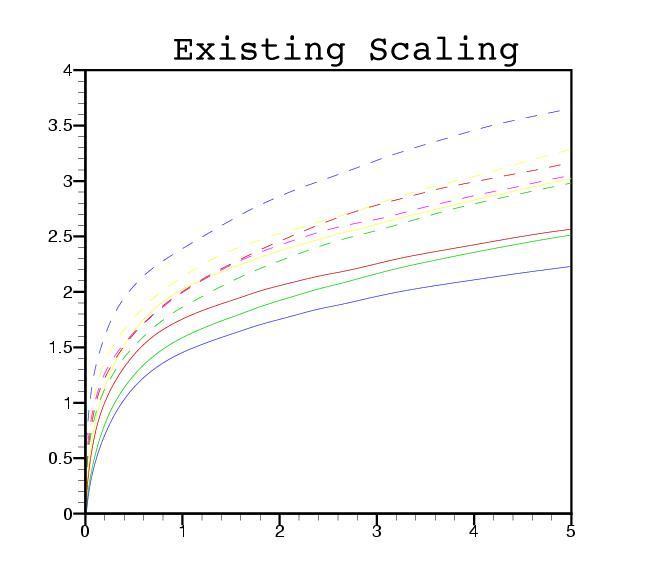
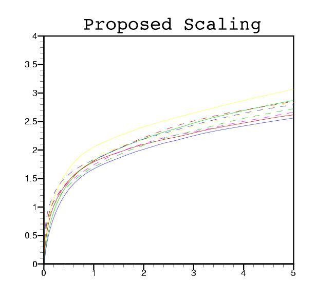
Figure: Proposed scaling decreases the scatter significantly.
Objectives
- Investigation of the sensitivity of jet trajectory to jet and
crossflow velocity profiles.
- Scaling law for jet trajectory that accounts for different boundary conditions.
- Controlled Numerical Simulations at different velocity ratios, jet
velocity profiles, and crossflow velocity profiles.
- Trajectory depends significantly on the jet and crossflow velocity
profiles, in addition to the velocity ratio.
- At the same r, a jet with a parabolic (high centerline velocity) profile issuing into a thick crossflow (greater boundary layer thickness) results in the highest trajectory.
- Suman Muppidi & Krishnan Mahesh 2005
Study of trajectories of jets in crossflow using direct numerical simulations
Journal of Fluid Mechanics, vol. 530, pages : 81 - 100.
DNS of a Fully turbulent jet in crossflow
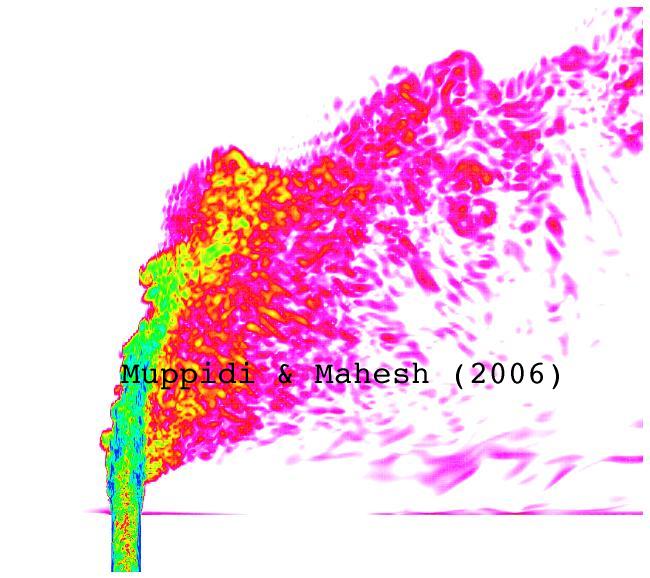
Figure: Contours of vorticity on the symmetry plane.
Objectives
- Study of the velocity field of a round turbulent jet in a laminar
crossflow.
- Comments on the ability of existing engineering models to predict this flow.
- Time dependent boundary conditions enable simulation of a fully
turbulent jet.
- Unstructured computational mesh consists of 11 Million elements.
- First time detailed comparison of velocity field with experiment.
- Computation of quantities like turbulence timescales, turbulent kinetic energy budget, etc.
- Suman Muppidi & Krishnan Mahesh 2007
Direct numerical simulation of round turbulent jets in crossflow
Journal of Fluid Mechanics, vol. 574, pages : 59 - 84.
- Suman Muppidi & Krishnan Mahesh 2005
Direct numerical simulation of turbulent jets in crossflow
Proceedings 43rd AIAA Aerospace Sciences Meeting and Exhibit, Reno, Nevada
AIAA paper 2005-1115.
- Suman Muppidi & Krishnan Mahesh 2005
Velocity field of a round turbulent transverse jet
Proceedings Fourth International symposium on Turbulence and Shear Flow Phenomena, Williamsburg, Virginia
Paper TSFP4-197, pages : 829-834.
Passive Scalar Mixing and Transport
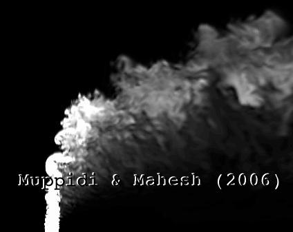
Figure: Contours of passive scalar on the symmetry plane.
White indicates unmixed jet fluid and black indicates unmixed crossflow fluid.
Objective
- Study of entrainment and mixing characteristics in transverse jets.
- Direct numerical simulations of momentum and passive scalar
transport.
- Passive scalar computation using a second order spatial
discretization scheme.
- Unstructured computational mesh consists of 11 Million elements.
- Entrainment in a transverse jet significantly higher than in
a regular jet.
- Jet entrains more crossflow fluid on the leeward side than on the windward side.
- Explained the observed entrainment features in terms of the local velocity
and pressure fields.
- Suman Muppidi & Krishnan Mahesh 2006
Passive scalar transport and mixing in turbulent jets in crossflow
Journal of Fluid Mechanics, vol. 598, pages : 335 - 360.
- Suman Muppidi & Krishnan Mahesh 2006
Passive scalar mixing in jets in crossflow
Proceedings 44th AIAA Aerospace Sciences Meeting and Exhibit, Reno, Nevada
AIAA paper 2006-1098.
Two-dimensional model problem to study CVP formation
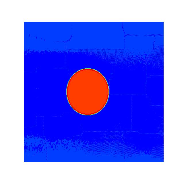
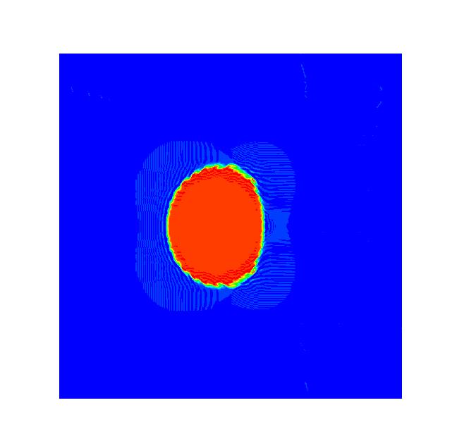
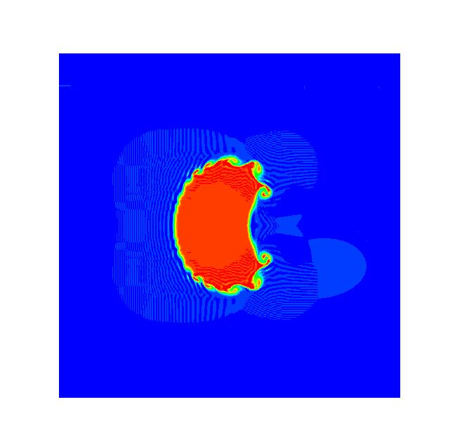
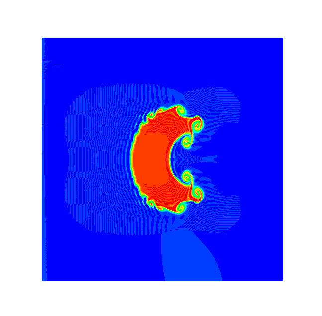
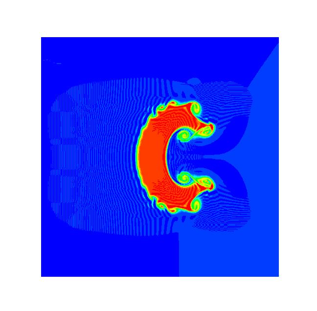
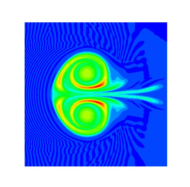
Figure: Cross-section of the two-dimensional jet at various times.
Solution yields deformation in shape and the formation of the counter-rotating vortex pair.
Objective
- The Counter-rotating Vortex Pair (CVP) has been regarded as a signature feature of this flow. However, the formation of the CVP is not yet resolved.
- Does a CVP form in 2-dimensions?
- Is a pipe necessary to generate a CVP?
- Two-dimensional flow field initialized with a circular jet surrounded by crossflow fluid
(similar to the flow seen very close to the wall in a three-d jet in crossflow). - Evolution of the solution in time can be related to the spatial evolution of the jet in crossflow.
- Cross-section deformation in the 2-d problem qualitatively similar to that seen in a transverse jet.
- The solution yields a pair of concentrated vortices.
- Jet moves with a constant acceleration initially, and with a constant velocity at later times.
- Cross-section deformation and the CVP formation related to the acceleration the jet experiences
(due to the crossflow fluid).
- CVP forms even in two dimensions; pipe is not required.
- Jet evolution can be explained in terms of the initial acceleration the crossflow fluid imposes on the jet, and the resulting pressure field.
- Jet evolution depends on both the velocity ratio and the Reynolds number.
- Suman Muppidi & Krishnan Mahesh 2006
Two-dimensional model problem to explain counter-rotating vortex pair formation in a transverse jet
Physics of Fluids, vol 18 (2006).